


The short answer: an ammeter is connected in series and an ideal ammeter has zero resistance; a voltmeter is connected in parallel and an ideal voltmeter has infinite resistance. Both are made from a galvanometer: add a small shunt in parallel to get an ammeter, or a large resistance in series to get a voltmeter.
Questions on meters look easy, yet they catch students every year because the reasons behind the rules are never explained properly. Once you understand why an ammeter goes in series and a voltmeter in parallel, every MCQ on connection, ideal resistance, range and conversion becomes a ten-second answer.
This guide defines all three instruments, explains the connection rules and ideal resistances, shows how a galvanometer is converted into an ammeter and a voltmeter with worked numbers, and ends with five practice MCQs.
What are a galvanometer, an ammeter and a voltmeter?
- Galvanometer: a very sensitive instrument that detects and measures small currents, typically microamperes to a few milliamperes. A centre-zero galvanometer also shows the direction of the current.
- Ammeter: an instrument that measures the current through a part of a circuit, in amperes (A). It is a galvanometer with a low-resistance shunt connected in parallel with it.
- Voltmeter: an instrument that measures the potential difference (PD) between two points, in volts (V). It is a galvanometer with a high resistance connected in series with it.
In formulas below, the galvanometer's coil resistance is Rg and the current that makes it deflect fully across its scale (the full-scale deflection current) is Ig.
The principle of a moving coil galvanometer
A current-carrying coil placed in a magnetic field experiences a torque. In a moving coil galvanometer, a rectangular coil of N turns and area A hangs in the field B of a permanent magnet. Curved pole pieces and a soft-iron core make the field radial, so the plane of the coil always lies along the field and the deflecting torque is simply:
Deflecting torque: τ = BINA. The suspension or spring twists back with a restoring torque cθ, where c is the torsion constant. At rest, BINA = cθ, so I = (c ÷ BAN) × θ: the deflection θ is proportional to the current, which gives an evenly spaced scale.
A galvanometer is more sensitive when a small current produces a large deflection, that is when θ ÷ I = BAN ÷ c is large: a strong field, many turns, a large coil and a weak suspension.
How is an ammeter connected in a circuit, and why in series?
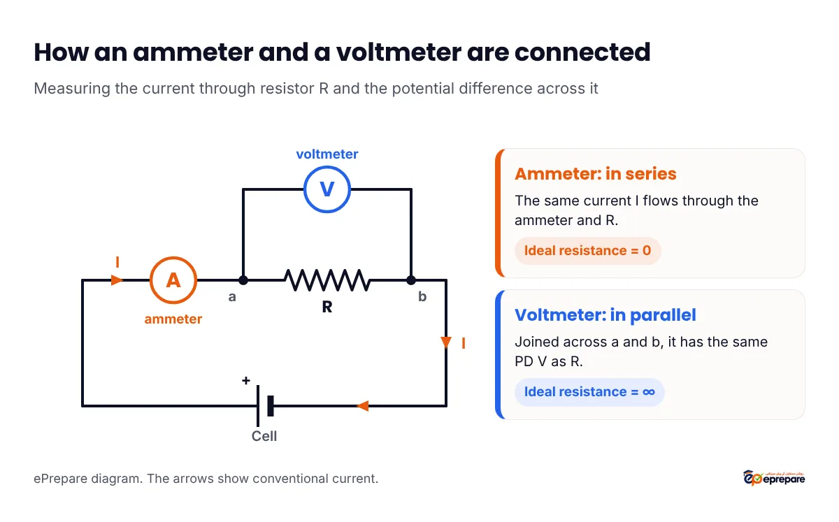
An ammeter is always connected in series with the component whose current you want, so that the same current flows through both. In a series path the current is the same at every point, so whatever passes through the resistor must also pass through the meter.
Why does an ideal ammeter have zero resistance?
Because it is in series, the ammeter's own resistance adds to the circuit's total resistance. Any resistance it has lowers the current it is trying to measure and uses up part of the voltage (a drop of I × RA). To read the current exactly as it would be without the meter, the ammeter must add nothing, so the resistance of an ideal ammeter is zero. Real ammeters get close by having a resistance far smaller than the rest of the circuit.
Example: a 12 V cell (no internal resistance) drives current through a 6 Ω resistor. The true current is 12 ÷ 6 = 2 A. An ammeter of 0.5 Ω in series makes the total 6.5 Ω, so it reads 12 ÷ 6.5 ≈ 1.85 A, not 2 A.
Why is a voltmeter connected in parallel?
Potential difference is measured between two points. Components connected in parallel have the same PD across them, so a voltmeter connected across the two ends of a resistor shows the PD across that resistor. That is why a voltmeter is always connected in parallel, never in series.
What is the resistance of an ideal voltmeter?
A voltmeter in parallel opens a second path for current. Whatever current it takes is stolen from the component, which changes the very PD being measured. To draw no current at all, the resistance of an ideal voltmeter is infinite. Real voltmeters have a resistance much larger than the component they are across.
Example: two 10 kΩ resistors in series across a 12 V cell share the voltage equally, 6 V each. Connect a voltmeter of 10 kΩ across one of them: that resistor and the meter together make 10 × 10 ÷ (10 + 10) = 5 kΩ, so the circuit is now 5 kΩ + 10 kΩ = 15 kΩ and the meter reads 12 × 5 ÷ 15 = 4 V instead of 6 V. A voltmeter of very high resistance would read almost exactly 6 V.
What happens if you connect them the wrong way?
- Ammeter in parallel: its very low resistance short-circuits the component. A large current flows through the ammeter, which can burn it out or damage the source.
- Voltmeter in series: its very high resistance cuts the current almost to zero. The circuit stops working and the voltmeter reads nearly the full voltage of the source, because almost all of it drops across the meter.
Ammeter vs voltmeter vs galvanometer: comparison table
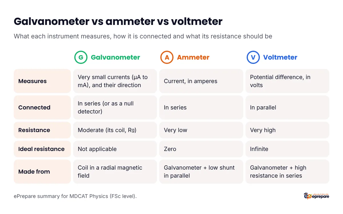
| Feature | Galvanometer | Ammeter | Voltmeter |
|---|---|---|---|
| Measures | Very small currents (μA to mA), and their direction | Current, in amperes | Potential difference, in volts |
| Connected | In series (or as a null detector) | In series | In parallel |
| Resistance | Moderate (its coil, Rg) | Very low | Very high |
| Ideal resistance | Not applicable | Zero | Infinite |
| Made from | Coil in a radial magnetic field | Galvanometer + low shunt in parallel | Galvanometer + high resistance in series |
What is the difference between an ammeter and a galvanometer?
A galvanometer is the sensitive heart of both meters: it detects tiny currents and reaches full scale at a small current Ig. An ammeter is a galvanometer that has been given a shunt so it can carry much larger currents safely, and its scale is calibrated in amperes. The shunt also makes the ammeter's total resistance very low, which a bare galvanometer's is not.
Converting a galvanometer into an ammeter (shunt)
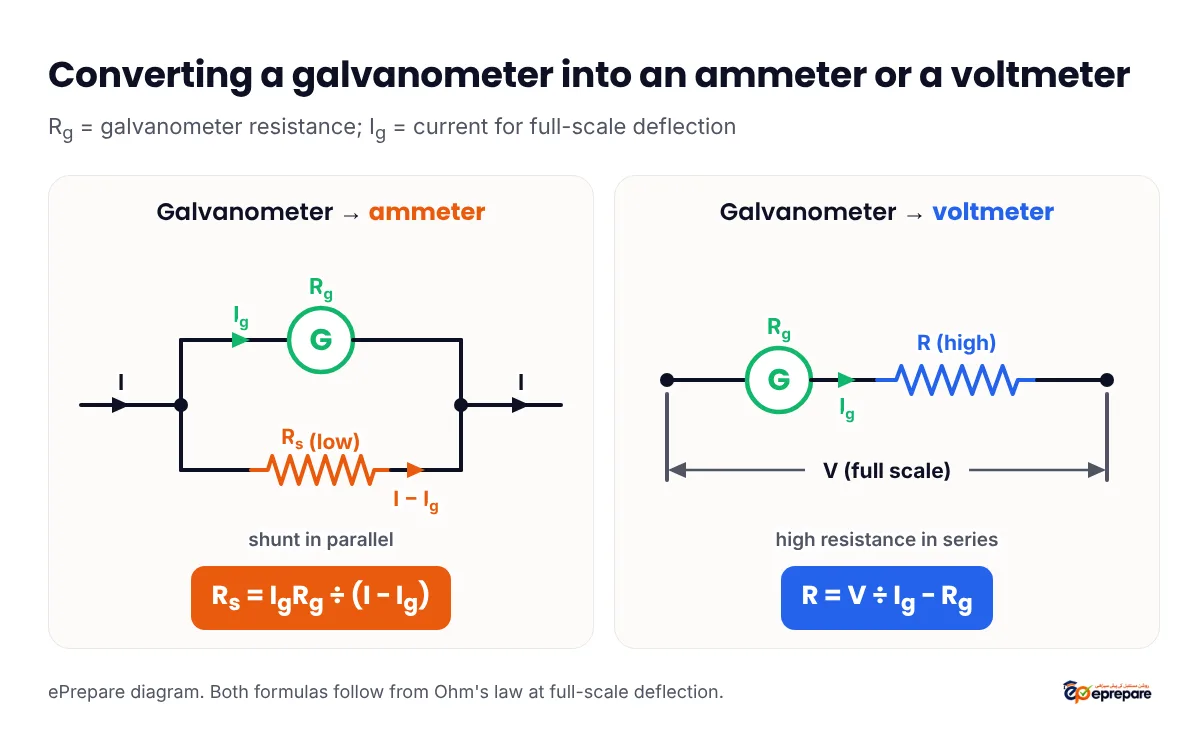
To measure a current I that is larger than Ig, connect a small resistance Rs, called a shunt, in parallel with the galvanometer. At full scale, Ig goes through the galvanometer and the rest, I − Ig, goes through the shunt. Parallel branches have the same PD, so:
Shunt formula: IgRg = (I − Ig)Rs, so Rs = IgRg ÷ (I − Ig). The ammeter's total resistance is RA = RgRs ÷ (Rg + Rs), which works out to IgRg ÷ I.
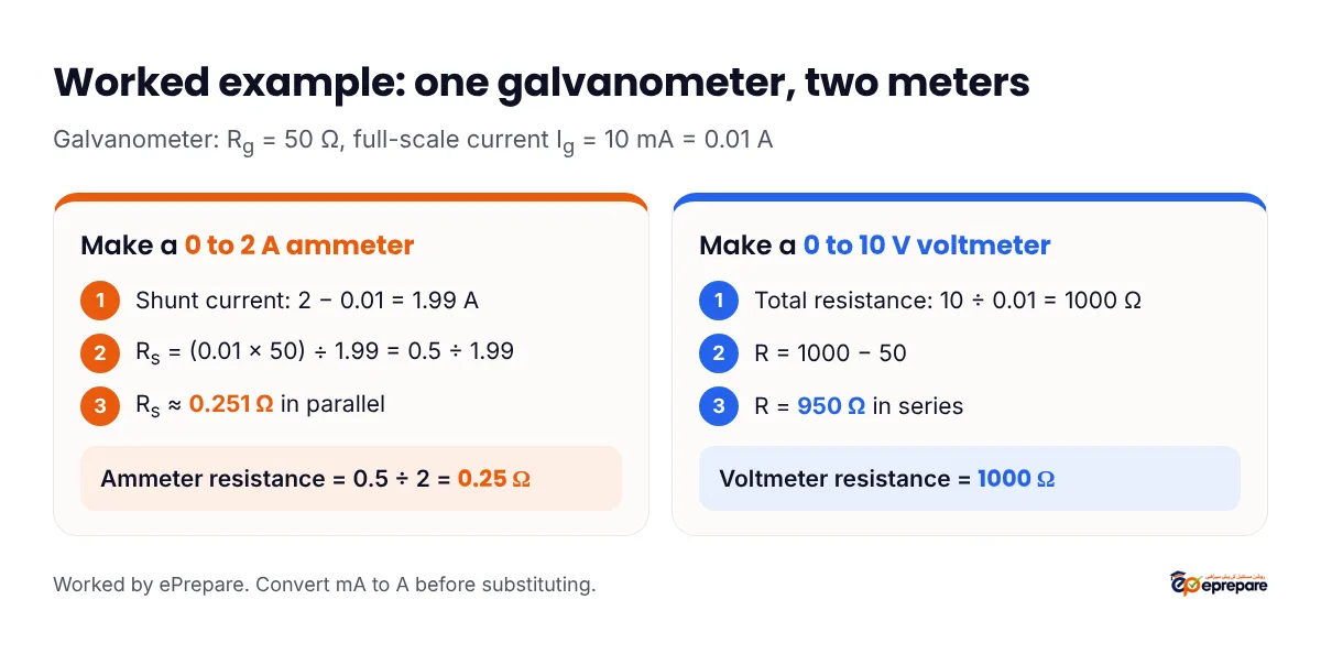
Worked example 1: a 2 A ammeter
A galvanometer has Rg = 50 Ω and gives full-scale deflection at Ig = 10 mA. Convert it into an ammeter of range 0 to 2 A.
- Convert to SI: Ig = 10 mA = 0.01 A.
- Current through the shunt at full scale: I − Ig = 2 − 0.01 = 1.99 A.
- Rs = IgRg ÷ (I − Ig) = (0.01 × 50) ÷ 1.99 = 0.5 ÷ 1.99 ≈ 0.251 Ω, in parallel.
- Resistance of the new ammeter: RA = IgRg ÷ I = 0.5 ÷ 2 = 0.25 Ω, far lower than the 50 Ω galvanometer.
What is the range of an ammeter?
The range of an ammeter is the maximum current it can measure, the current that sends its pointer to full scale. A 0 to 5 A ammeter has a range of 5 A. Range is not the same as the smallest division on the scale (the least count).
The range is set by the shunt. If you want the range to be n times the galvanometer's full-scale current (I = nIg), the shunt formula becomes:
Range shortcut: Rs = Rg ÷ (n − 1). A smaller shunt gives a larger range and a lower ammeter resistance. For a voltmeter, multiplying the range by n needs a series resistance R = (n − 1)Rg.
Example: a galvanometer of 90 Ω must carry only one-tenth of the main current, so n = 10. The shunt is 90 ÷ (10 − 1) = 10 Ω. Check: the galvanometer and shunt share the current in the ratio 10 : 90, that is 1 : 9, so the galvanometer carries 1/10 of it.
Converting a galvanometer into a voltmeter (series resistor)
To measure a PD up to V, connect a high resistance R in series with the galvanometer. At full scale the current through both is Ig, so V = Ig(Rg + R):
Series resistor formula: R = V ÷ Ig − Rg. The voltmeter's total resistance is Rg + R = V ÷ Ig, which is large.
Worked example 2: a 10 V voltmeter
Take the same galvanometer (Rg = 50 Ω, Ig = 0.01 A) and convert it into a voltmeter of range 0 to 10 V.
- Total resistance needed: V ÷ Ig = 10 ÷ 0.01 = 1000 Ω.
- Series resistance: R = 1000 − 50 = 950 Ω, in series.
- Check: at 10 V the current is 10 ÷ (50 + 950) = 0.01 A, exactly full scale.
MDCAT shortcuts and common traps
Shortcuts and traps. (1) Ammeter: series, small resistance, shunt in parallel. Voltmeter: parallel, huge resistance, resistor in series. (2) Ideal ammeter R = 0; ideal voltmeter R = ∞. (3) Convert mA and μA to amperes before substituting. (4) Do not forget to subtract Rg in R = V ÷ Ig − Rg: 10 ÷ 0.01 = 1000 Ω is the total, not the resistor. (5) The shunt for n times the range is Rg ÷ (n − 1), not Rg ÷ n. (6) An ammeter's resistance is lower than its shunt's, because parallel resistance is less than the smallest branch.
Where this sits in the syllabus: meters are FSc Part 2 physics. PM&DC's MDCAT curriculum does not list the galvanometer as a separate learning outcome, but meter questions are built on what it does list in Current electricity, Ohm's law and the internal resistance of sources. Check every unit on the MDCAT syllabus page, and see how Current electricity ranks in MDCAT Physics high-yield chapters and formula sheet.
Practice MCQs: ammeter, voltmeter and galvanometer
Question 1
The resistances of an ideal ammeter and an ideal voltmeter are, respectively:
- zero and zero
- zero and infinite
- infinite and zero
- infinite and infinite
Show answer
Answer: B, zero and infinite. The ammeter is in series, so it must add no resistance; the voltmeter is in parallel, so it must draw no current.
Question 2
A galvanometer of resistance 100 Ω gives full-scale deflection at 1 mA. What shunt converts it into an ammeter of range 0 to 1 A?
- About 0.1 Ω in parallel
- About 1 Ω in parallel
- 999 Ω in series
- 9900 Ω in series
Show answer
Answer: A, about 0.1 Ω in parallel. Rs = IgRg ÷ (I − Ig) = (0.001 × 100) ÷ 0.999 = 0.1 ÷ 0.999 ≈ 0.1 Ω. A shunt always goes in parallel.
Question 3
The same galvanometer (100 Ω, 1 mA) is to be converted into a voltmeter of range 0 to 10 V. What is needed?
- 9900 Ω in parallel
- 9900 Ω in series
- 10,000 Ω in series
- 0.1 Ω in parallel
Show answer
Answer: B, 9900 Ω in series. R = V ÷ Ig − Rg = 10 ÷ 0.001 − 100 = 10,000 − 100 = 9900 Ω. 10,000 Ω is the voltmeter's total resistance, the common trap.
Question 4
Two 10 kΩ resistors are connected in series across a 12 V cell of negligible internal resistance. A voltmeter of resistance 10 kΩ is connected across one resistor. What does it read?
- 6 V
- 4 V
- 8 V
- 3 V
Show answer
Answer: B, 4 V. The meter and the resistor in parallel make 5 kΩ, so the total is 15 kΩ and the meter's share is 12 × 5 ÷ 15 = 4 V. An ideal (infinite-resistance) voltmeter would read 6 V.
Question 5
A galvanometer has a resistance of 45 Ω. What shunt makes only 10% of the main current pass through the galvanometer?
- 4.5 Ω
- 5 Ω
- 405 Ω
- 50 Ω
Show answer
Answer: B, 5 Ω. Here n = 10, so Rs = Rg ÷ (n − 1) = 45 ÷ 9 = 5 Ω. Check: the currents divide in the inverse ratio of resistances, 5 : 45 = 1 : 9, so the galvanometer gets 1 part in 10. 4.5 Ω (Rg ÷ n) is the trap.
For more, practise past-paper Physics questions with step-by-step solutions on our free MDCAT Physics MCQs page. Related explainers: capacitors and equivalent capacitance and EMF, Lenz's law, Fleming's rules and SHM.
Frequently asked questions
What is the range of an ammeter?
The range of an ammeter is the maximum current it can measure, the current that gives full-scale deflection. A 0 to 5 A ammeter has a range of 5 A. A smaller shunt gives a larger range.
How is an ammeter connected in a circuit?
In series with the component whose current is being measured, so that the same current flows through the ammeter and the component.
Why does an ideal ammeter have zero resistance?
Because it is in series, any resistance it has would reduce the current it is measuring and take part of the voltage. Zero resistance means the meter does not change the circuit at all.
Why is a voltmeter connected in parallel?
A voltmeter measures the potential difference between two points, and components in parallel have the same potential difference. Connected across a component, it reads that component's PD.
What is the resistance of an ideal voltmeter?
Infinite. An ideal voltmeter draws no current, so it does not change the potential difference it is measuring.
What is the difference between an ammeter and a galvanometer?
A galvanometer detects and measures very small currents (microamperes to milliamperes) and has a moderate coil resistance. An ammeter is a galvanometer with a low-resistance shunt in parallel, so it measures larger currents in amperes and has a very low total resistance.
How is a galvanometer converted into an ammeter?
By connecting a low resistance (shunt) in parallel with it, of value Rs = IgRg ÷ (I − Ig). To make a voltmeter instead, connect a high resistance R = V ÷ Ig − Rg in series.
What is the principle of a moving coil galvanometer?
A current-carrying coil in a magnetic field experiences a torque, τ = BINA in a radial field. The coil turns until the restoring torque of the suspension balances it, so the deflection is proportional to the current.
Practise Physics with ePrepare
Meters, circuits and electrostatics reward students who understand the reasons, not just the formulas. Register on ePrepare for Physics lectures, chapter-wise MCQs with worked explanations and full-length papers that build your speed for exam day.
Sources: PM&DC Uniform Curriculum MDCAT (hosted by KMU) for the syllabus units. All formulas are derived in this article from Ohm's law and the rules for series and parallel circuits; every number in the examples and MCQs is worked here.